High Availability
What is a HA
High Availability (HA) in both Backup_node and Master_node refers to the capability of the nodes to ensure uninterrupted operation and minimal downtime. In the context of networking, HA involves redundant systems and failover mechanisms that automatically switch to backup nodes in case of primary node failure. This ensures continuous access to services and resources, even during hardware or software failures. HA setups typically employ techniques like load balancing, clustering, and data replication to distribute workload and maintain service availability. In essence, HA in both Backup_node and Master_node enhances reliability, resilience, and fault tolerance in network infrastructures, crucial for critical applications and services.
Why do we need HA Configuration
High Availability (HA) in both Backup_node and Master_node is essential to ensure uninterrupted operation of critical systems and services. HA setups provide redundancy and failover mechanisms that automatically switch to backup nodes in case of primary node failure. This reduces downtime, ensuring continuous access to resources and services for users. HA also enhances reliability, resilience, and fault tolerance in network infrastructures, crucial for maintaining productivity and meeting service level agreements. Additionally, HA minimizes the risk of data loss and ensures business continuity, making it indispensable for organizations relying on continuous operation of their IT infrastructure.
Interface Configuration on Master_node & Backup_node
1. Configuring Network Interface For Master_node & Backup_node
-
Master_node
-
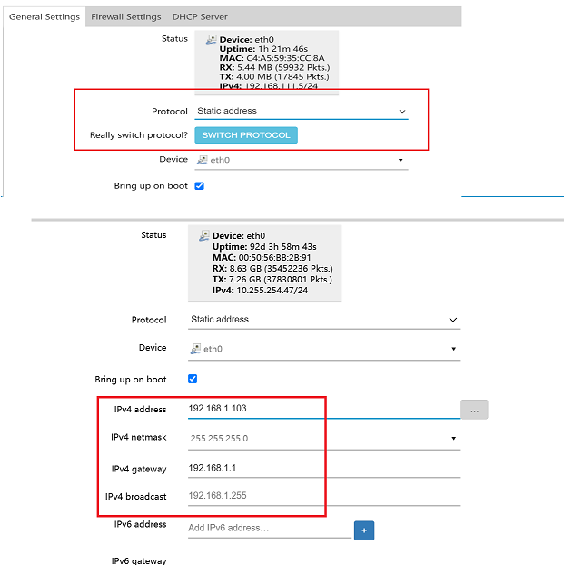
Login to the UI of the Master_node using the provided IP address.

-
Navigate to Network > Interface Menu > Select and edit the eth0 interface.
-
Fill in the specified details given there
- Protocol: Select the Static Address.
- Switch Protocol: Click on Switch Protocol and proceed to fill in the new fields.
- IPv4 Address: Enter the IPv4 address for Ex:192.168.1.102
- IPv4 Netmask: Select IPv4 netmask for Ex: 255.255.255.0
- IPv4 Gateway: Enter the IPv4 gateway for Ex: 192.168.1.1
- IPv4 Broadcast: Enter the IPv4 broadcast. IPv4 broadcast comes by default.
-
Go to the Advanced Settings menu.
-
Custom DNS Servers: Enter the custom DNS server details, click the + icon, and then click on the Save button.
-
-
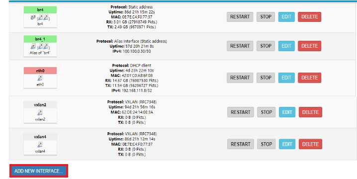
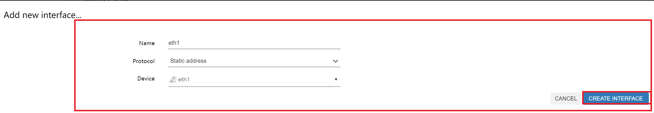
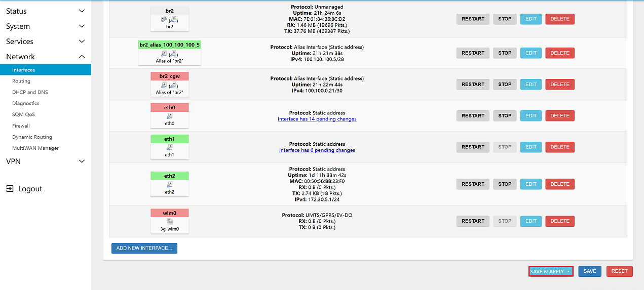
Go to the Interfaces Menu and click on ADD NEW INTERFACE.
-
Fill in the interface details:
- Name: Enter the Name for Ex: eth1.
- Protocol: Select the Protocol for Ex: Static address.
- Device: Enter the Device for Ex: eth1. Then click on CREATE INTERFACE.
-
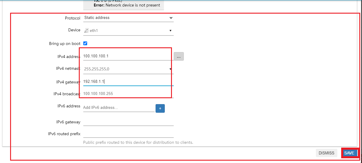
Configure the eth1 interface. Fill in the given details there:
- IPv4 Address: Enter the IPv4 address for Ex:100.100.100.1
- IPv4 Netmask: Select IPv4 netmask for Ex: 255.255.255.0
- IPv4 Gateway: Enter the IPv4 gateway for Ex: 192.168.1.1. IPv4 gateway comes by default.
- IPv4 Broadcast: Enter the IPv4 broadcast for Ex: 100.100.100.255. IPv4 broadcast comes by default. Click on the Save button.
-
Finally, click on SAVE & APPLY button.
-
Backup_node
-
Login to the UI of the Backup_node using the provided IP address.
-
Navigate to Network > Interface Menu > Select and edit the eth0 interface.
-
Fill in the specified details given there
- Protocol: Select the Static Address.
- Switch Protocol: Click on Switch Protocol and proceed to fill in the new fields.
- IPv4 Address: Enter the IPv4 address for Ex:192.168.1.103
- IPv4 Netmask: Select IPv4 netmask for Ex: 255.255.255.0
- IPv4 Gateway: Enter the IPv4 gateway for Ex: 192.168.1.1
- IPv4 Broadcast: Enter the IPv4 broadcast. IPv4 broadcast comes by default.
-
Go to the Advanced Settings menu.
-
Custom DNS Servers: Enter the custom DNS server details, click the + icon, and then click on the Save button.
-
-
Go to the Interfaces Menu and click on ADD NEW INTERFACE.
-
Fill in the interface details:
- Name: Enter the Name for Ex: eth1
- Protocol: Select the Protocol for Ex: Static address.
- Device: Enter the Device for Ex: eth 1. Then click on CREATE INTERFACE.
-
Configure the eth1 interface. Fill in the given details there:
- IPv4 Address: Enter the IPv4 address for Ex:100.100.100.2
- IPv4 Netmask: Select IPv4 netmask for Ex: 255.255.255.0
- IPv4 Gateway: Enter the IPv4 gateway for Ex: 192.168.1.1. IPv4 gateway comes by default.
- IPv4 Broadcast: Enter the IPv4 broadcast for Ex: 100.100.100.255. IPv4 broadcast comes by default. Click on the Save button.

-
- Finally, click on SAVE & APPLY button.
2. Creating Master and Backup Nodes
2.1. Creating a Master Node
To create a master node:
-
Navigate to Service menu > Keepalived menu > Globals Tab.
- Enter Router_ID where Router ID is given there for Ex:- Master_node. After click on Save & Apply button.

Select the Primary Node:
-
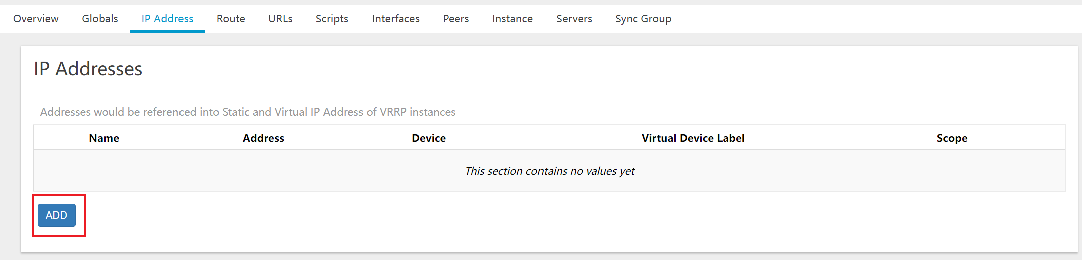
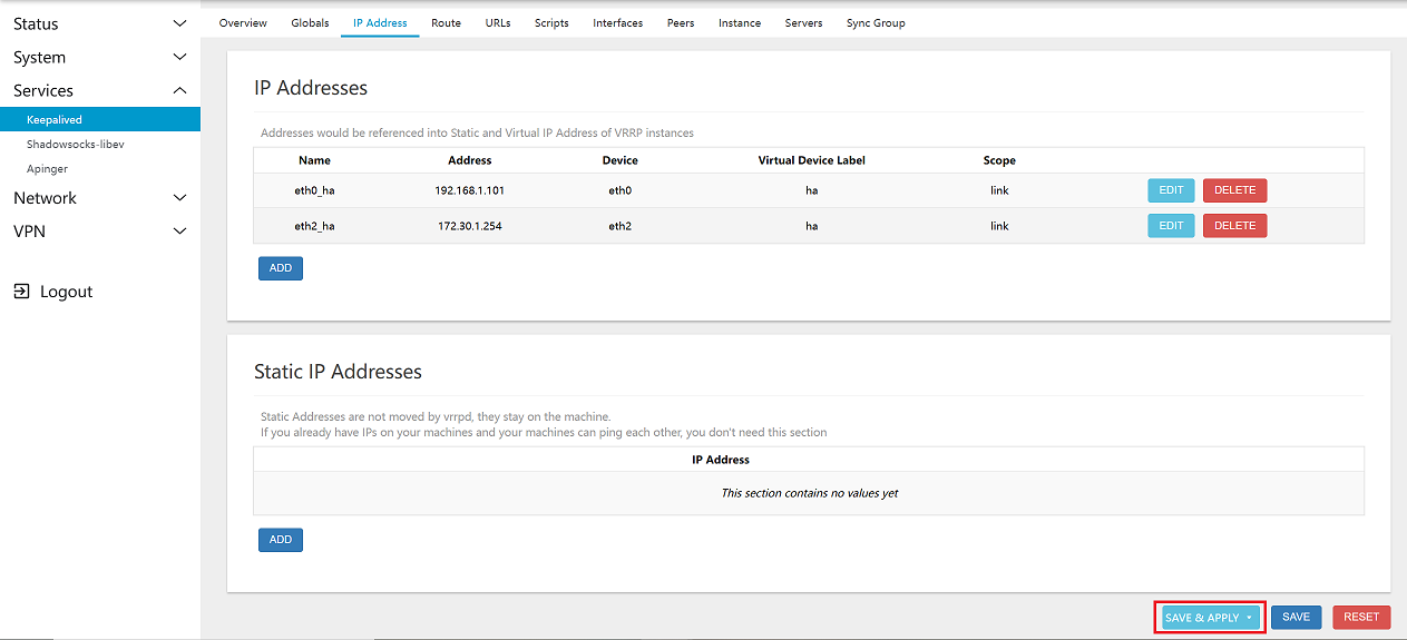
Go to the IP Address Tab and click on Add.
-
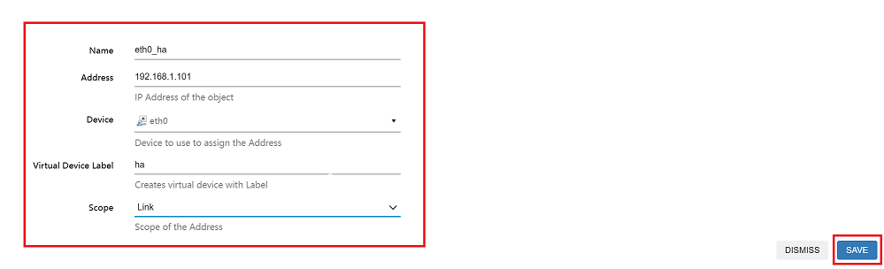
Fill in the details for eth0_ha:
- Name: Enter the Name for Ex:eth0_ha.
- Address: Provide the IP address, For example: 192.168.1.101, which represents a floating IP (Virtual IP).
- Device: Enter the Device for Ex:eth0
- Virtual Device Label: Enter the Virtual Device Label for Ex: ha.
- Scope: Enter the Scope for Ex:Link.
- After clicking on the Save button.
-
Repeat the same steps for eth2_ha and click on the Save & Apply button.
Assign Master Role:
-
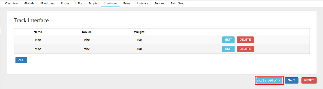
Go to the Interfaces Tab for Track Interface and click on Add button.
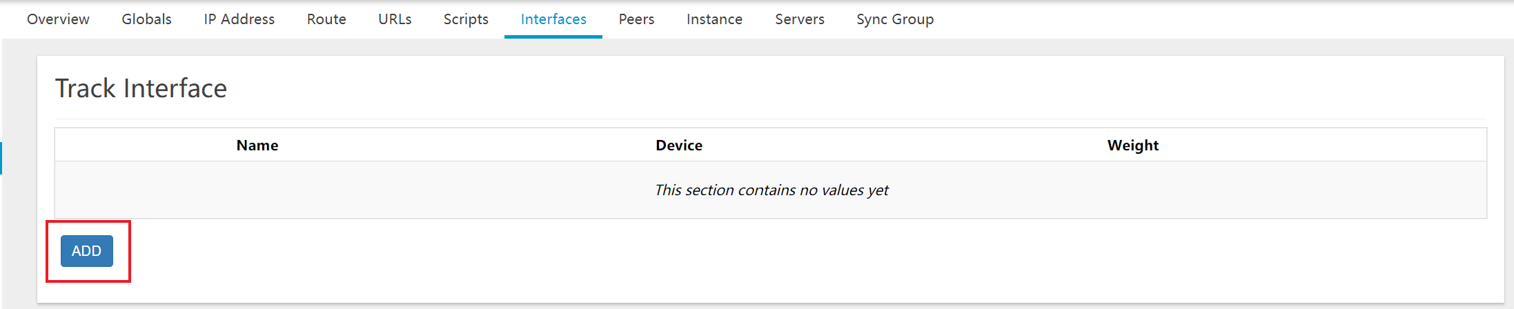
-
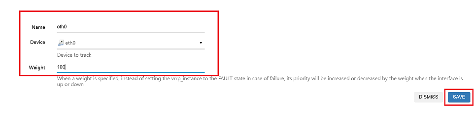
Fill in the details:
- Name: Enter the Name for Ex:eth0.
- Device: Enter the Device for Ex:eth0.
- Weight: Enter the Weight for Ex:100.
- After clicking on the Save button.
-
Repeat the same steps for eth2 and click on the Save & Apply button.
-
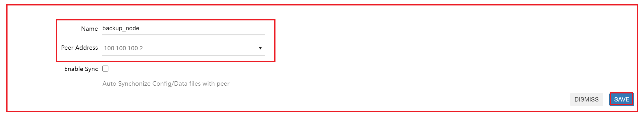
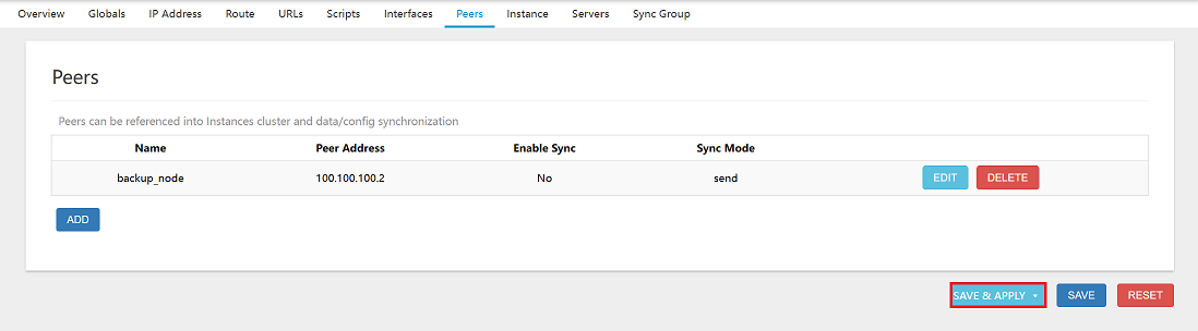
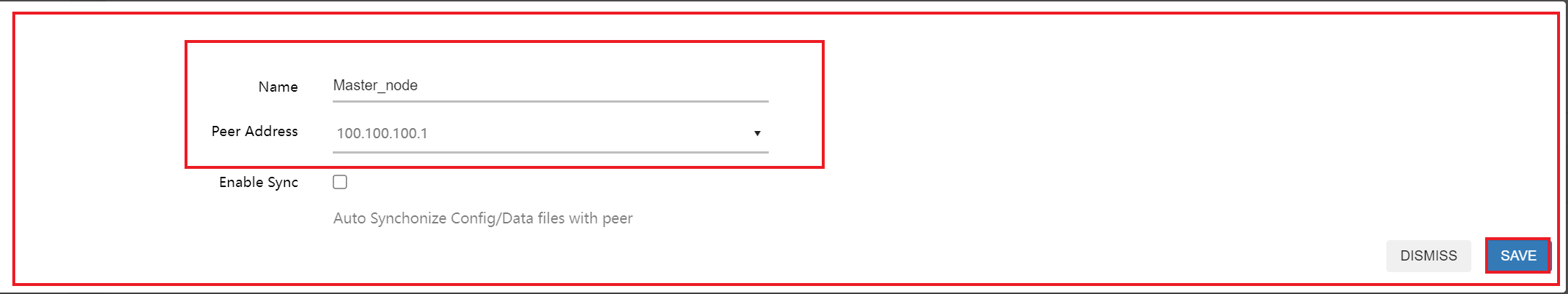
Go to the Peer Tab and click on the Add button.
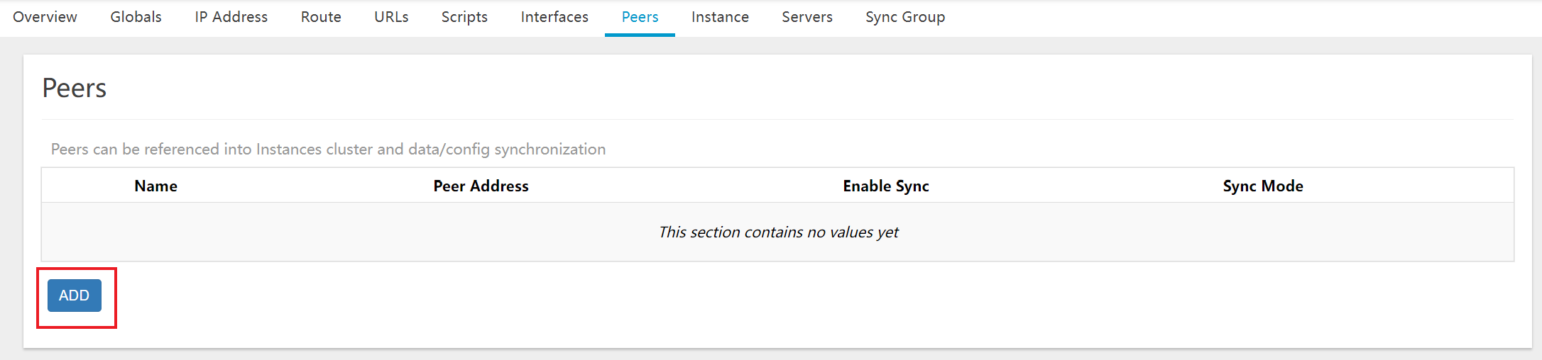
-
Fill in the details:
- Name: Enter the Name for Ex: Backup_node.
- Peers Address: Select the Peers Address. Navigate and Select custom enter IP 100.100.100.2 and press the Enter key.
- After clicking on the Save button.
-
Finally, click on SAVE & APPLY button.
Configure Heartbeat Settings:
-
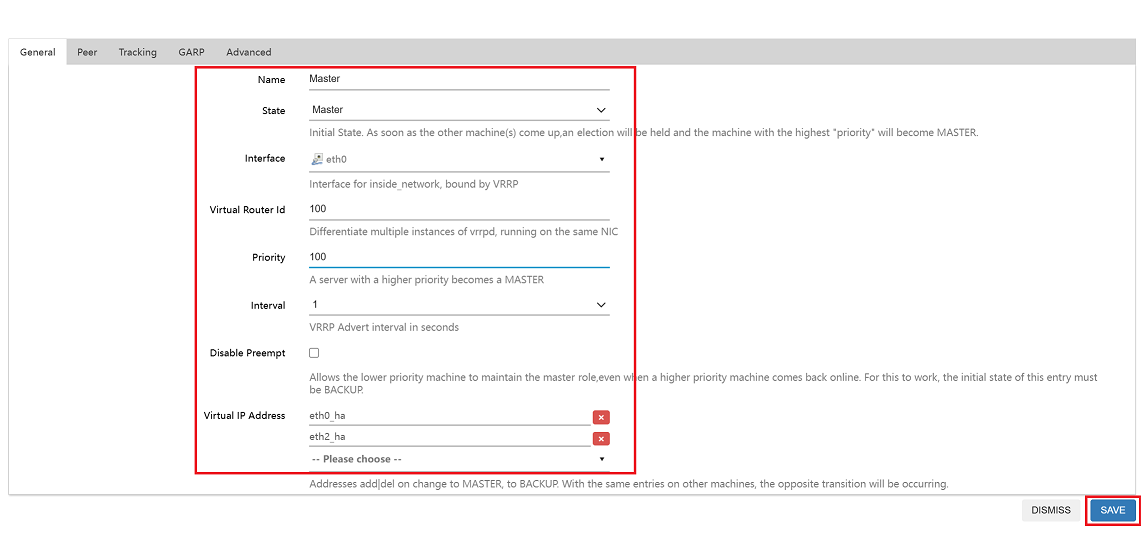
Navigate to the Instance Tab > VRRP Instance and click on Add button.
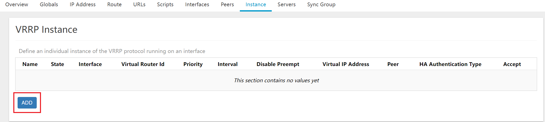
-
Fill in the VRRP instance details:
- Name: Enter the Name for Ex:Master.
- State:Enter the State for Ex:Master.
- Interface: Select the Interface for Ex:eth1.
- Virtual Router ID: Enter the Virtual Router ID for Ex:100
- Priority: Enter the Priority for Ex:100.
- Interval: Enter the Interval for Ex:1.
- Disable Preempt: Enter the Disable Preempt for Ex:na.
- Virtual IP Address: Select the Virtual IP Address. Navigate Select eth0_ha,eth2_ha
- After clicking on the Save button.
-
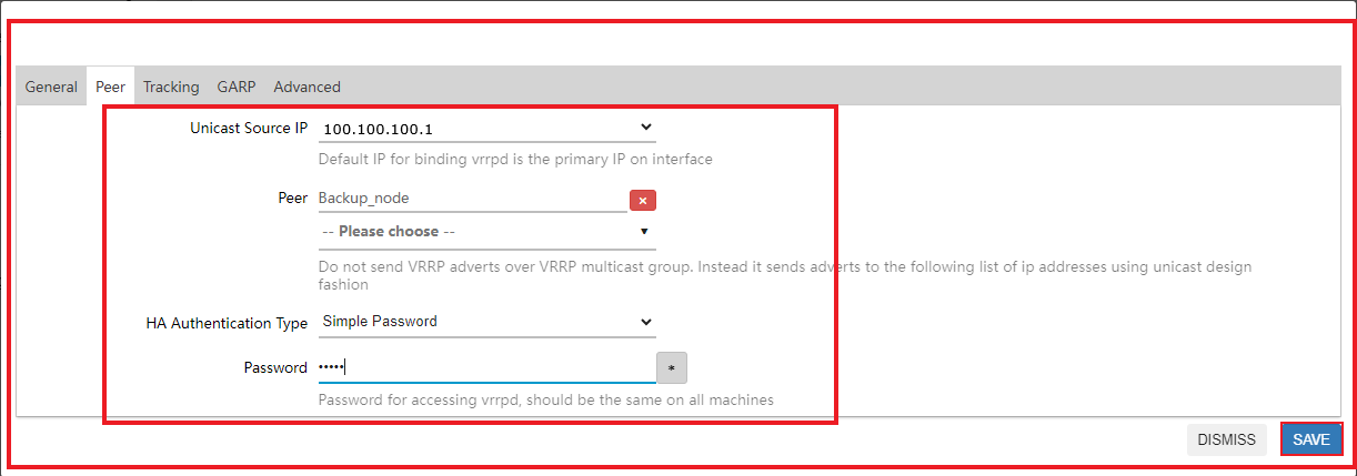
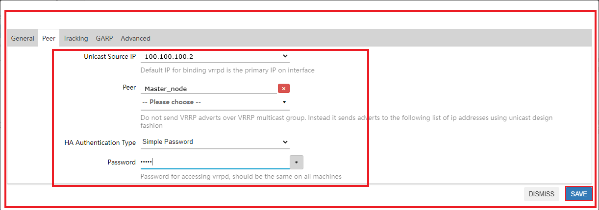
Go to the Peer section and fill in the details:
- Unicast Source IP: Navigate and Select 100.100.100.1
- Peer: Peer select Backup_node.
- HA Authentication Type: Select Simple Password.
- Password: Enter Password for Ex:admin.
- After clicking on the Save button.
-
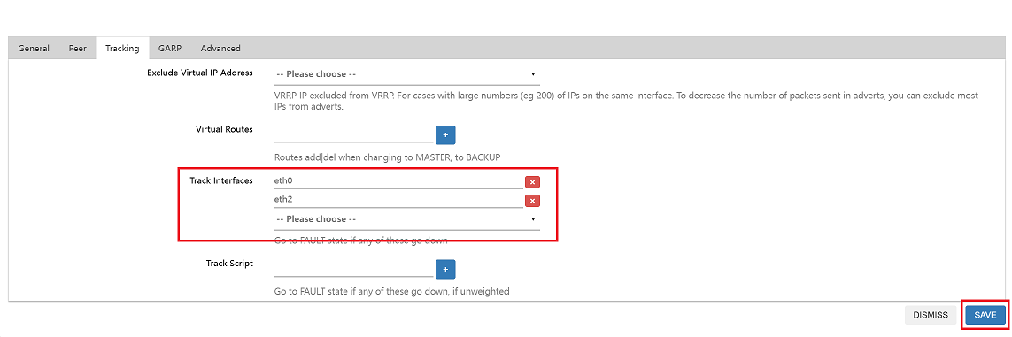
Go to the Track section and fill in the details:
- Track Interfaces: Select eth0 and eth2.
- After clicking on the Save button.
2.2. Creating a Backup_Node
To create a backup node:
-
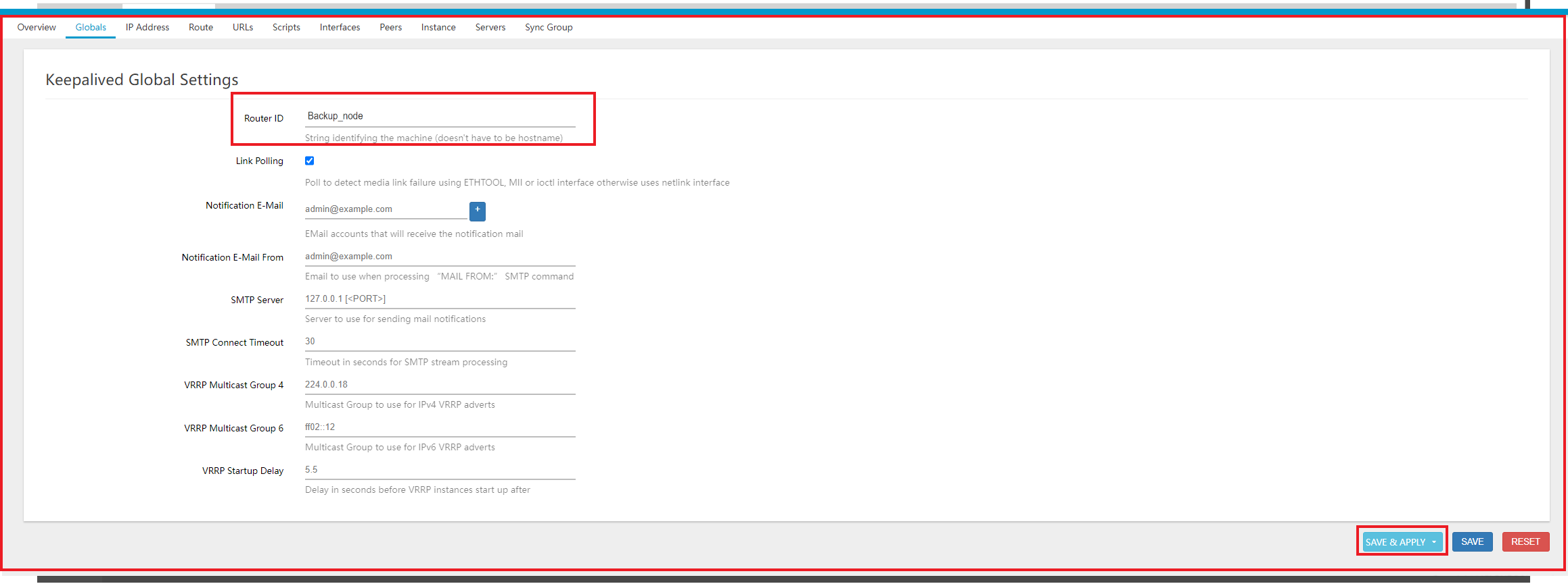
Navigate to Service menu > Keepalived menu > Globals Tab.
- Enter Router_ID where Router ID is given there for Ex:- Backup_node. After click on Save & Apply button.
Select the Primary Node:
-
Go to the IP Address Tab and click on Add button.
-
Fill in the details for eth0_ha:
- Name: Enter the Name for Ex:eth0_ha.
- Address: Enter the Address for Ex:192.168.1.101
- Device: Enter the Device for Ex:eth0
- Virtual Device Label: Enter the Virtual Device Label for Ex: ha.
- Scope: Enter the Scope for Ex:Link.
- After clicking on the Save button.
-
Repeat the same steps to create an IP Address for eth2_ha.
- Name: Enter the Name for Ex:eth2_ha.
- Address: Enter the Address for Ex: 172.30.1.254
- Device: Enter the Device for Ex:eth2
- Virtual Device Label: Enter the Virtual Device Label for Ex: ha.
- Scope: Enter the Scope for Ex:Link.
- After clicking on the Save button.
Assign Backup Role:
-
Go to the Interfaces Tab for Track Interface and click on Add button.
-
Fill in the details:
- Name: Enter the Name for Ex:eth0.
- Device: Enter the Device for Ex:eth0
- Weight: Enter the Weight for Ex:100.
- After clicking on the Save button.
-
Repeat the same steps for eth2 and click on the Save & Apply button.
-
Go to the Peer Tab and click on the Add button.
-
Fill in the details:
- Name: Enter the Name for Ex: Master_node.
- Peers Address: Select the Peers Address. Navigate and Select custom enter IP 100.100.100.1 and press the Enter key.
- After clicking on the Save button.
Configure Heartbeat Settings:
-
Navigate to the Instance Tab > VRRP Instance and click on Add button.
-
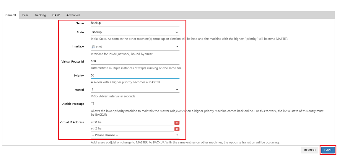
Fill in the VRRP instance details:
- Name: Enter the Name for Ex:Backup.
- State:Enter the State for Ex:Backup.
- Interface: Select the Interface for Ex:eth1.
- Virtual Router ID: Enter the Virtual Router ID for Ex:100.
- Priority: Enter the Priority for Ex:50.
- Interval: Enter the Interval for Ex:1.
- Disable Preempt: Enter the Disable Preempt for Ex:na.
- Virtual IP Address: Select the Virtual IP Address. Navigate Select eth0_ha,eth2_ha.
- After clicking on the Save button.
-
Go to the Peer section and fill in the details:
- Unicast Source IP: Navigate and Select 100.100.100.2
- Peer: Peer select Master_node.
- HA Authentication Type: Select Simple Password.
- Password: Enter Password for Ex:admin.
- After clicking on the Save button.
-
Go to the Track section and fill in the details:
- Track Interfaces: Select eth0 and eth2
- After clicking on the Save button.
Synchronization Settings for Master_Node & Backup_Node
-
Master_Node
-
Login to the UI:
- Access the Master Node UI using the provided IP address.
-
Navigate to Keepalived:
- From the main menu, go to the Services menu section.
- Select Keepalived menu from the Services menu.
- Click on the Script tab within the Keepalived window.
- Click on the Add button.
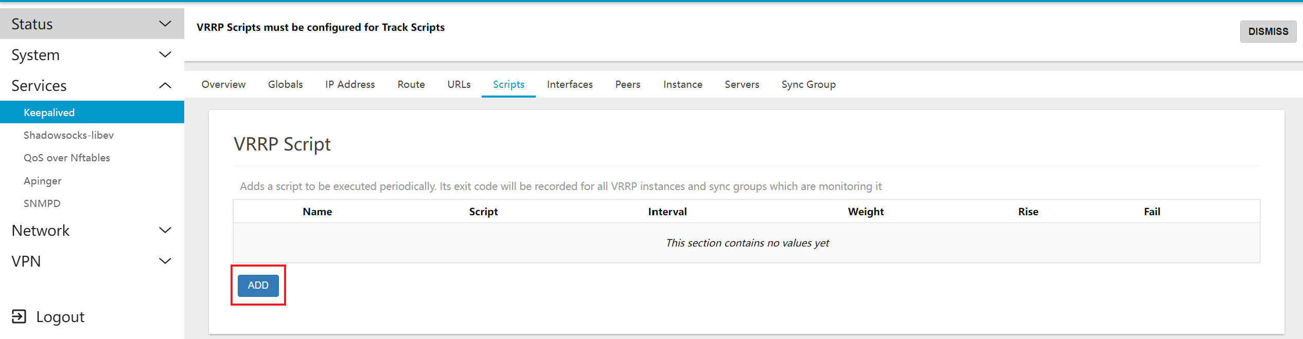
-
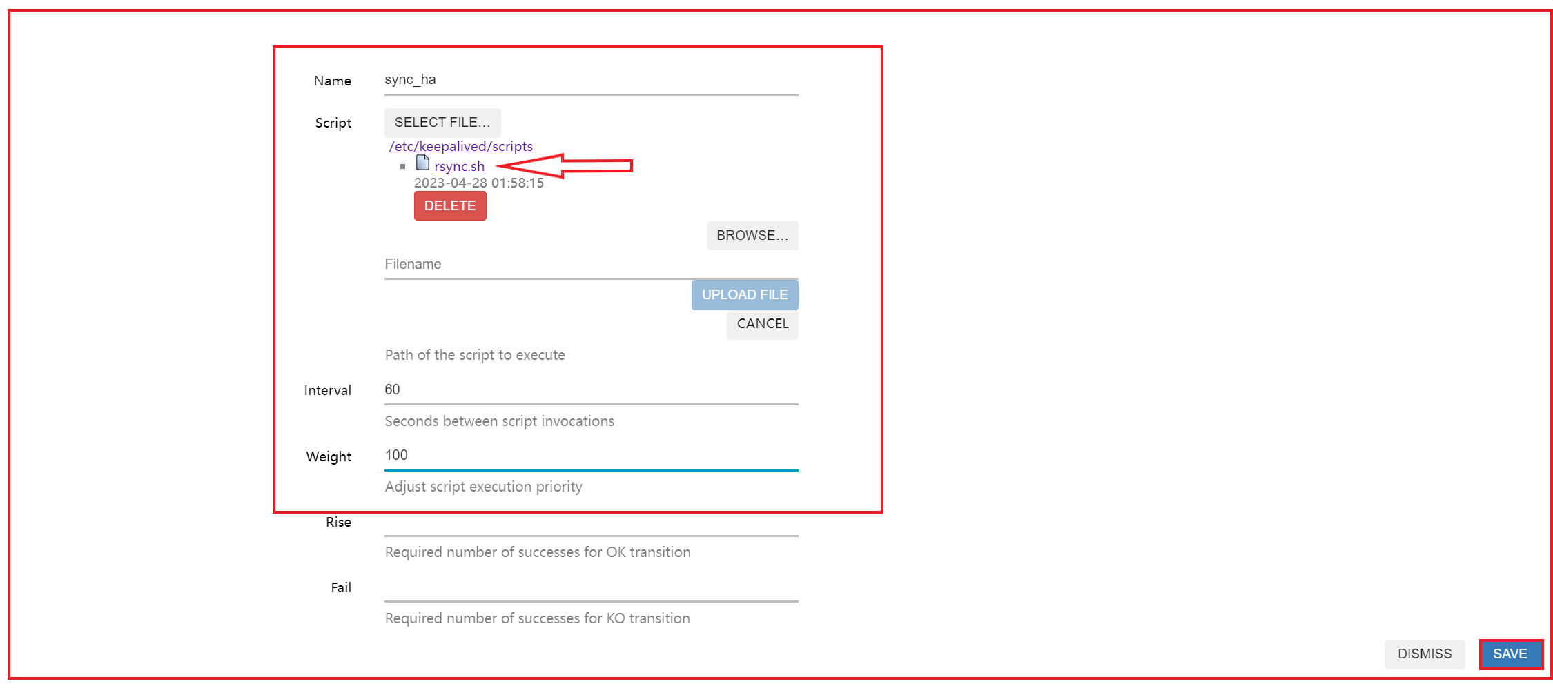
Fill in Script Details:
- Name: Enter the Name for Ex: sync_ha.
- Script: Click on Select file and choose file(By default file will appear there, you have to select)
- Interval: Interval which will be 60 by default.
- Weight: Enter the Weight for Ex: 100.
- After clicking on the Save button.
-
Click on SAVE & APPLY button to apply the new script configuration.
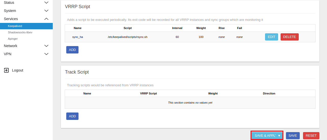
-
Click on the Add button under the Track Script section.
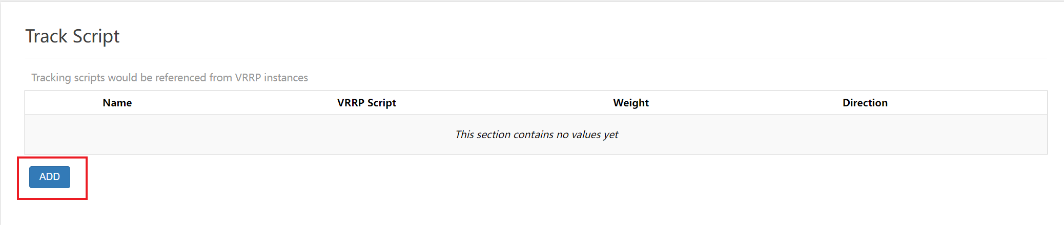
-
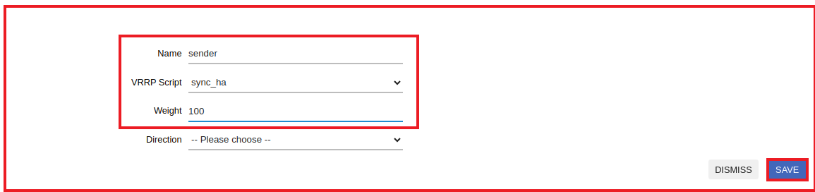
Enter Track Script Details.
- Name: Enter the Name for Ex:sender
- VRRP Script: Select sync_ha.
- Weight: Enter the Weight for Ex:100.
- After clicking on the Save button.
-
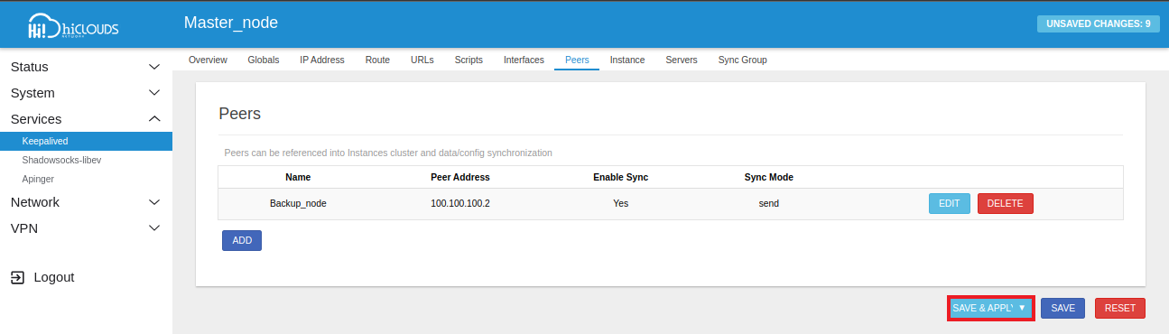
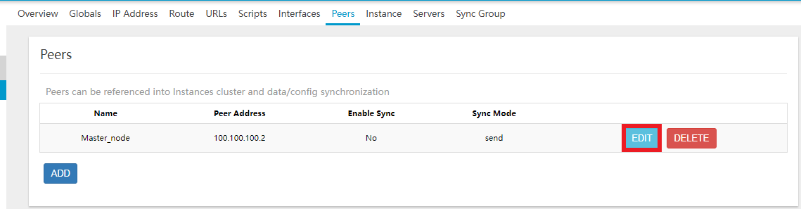
Go to the Peers tab and click on Edit button.
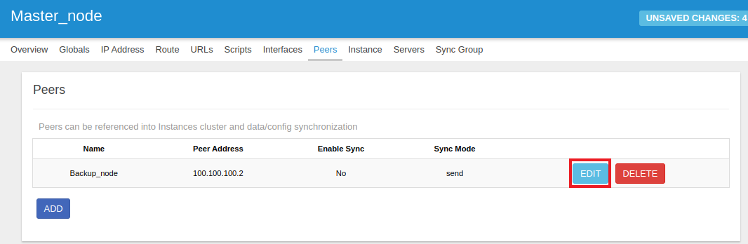
-
Check the Enable Sync box. And proceed to fill in the new fields.
-
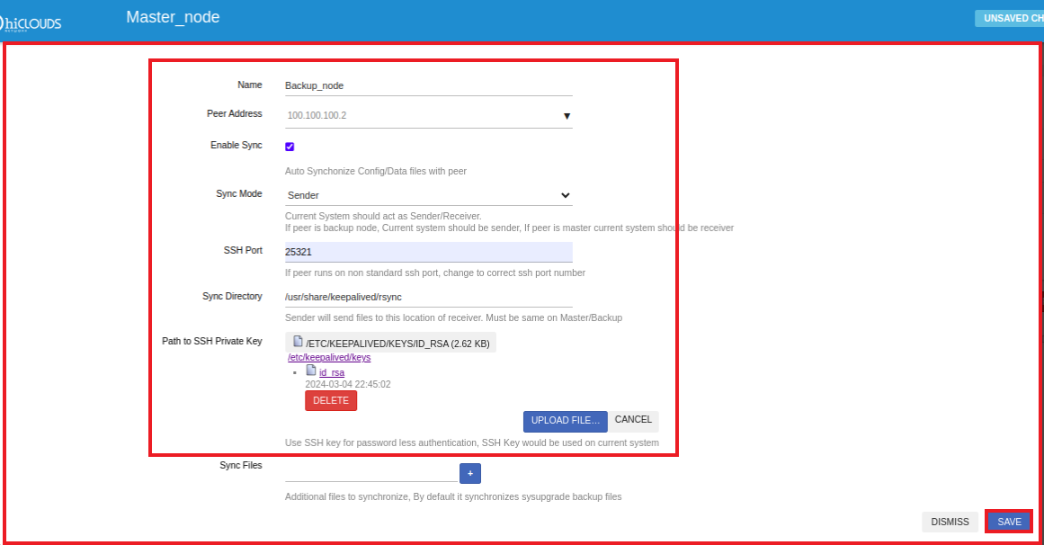
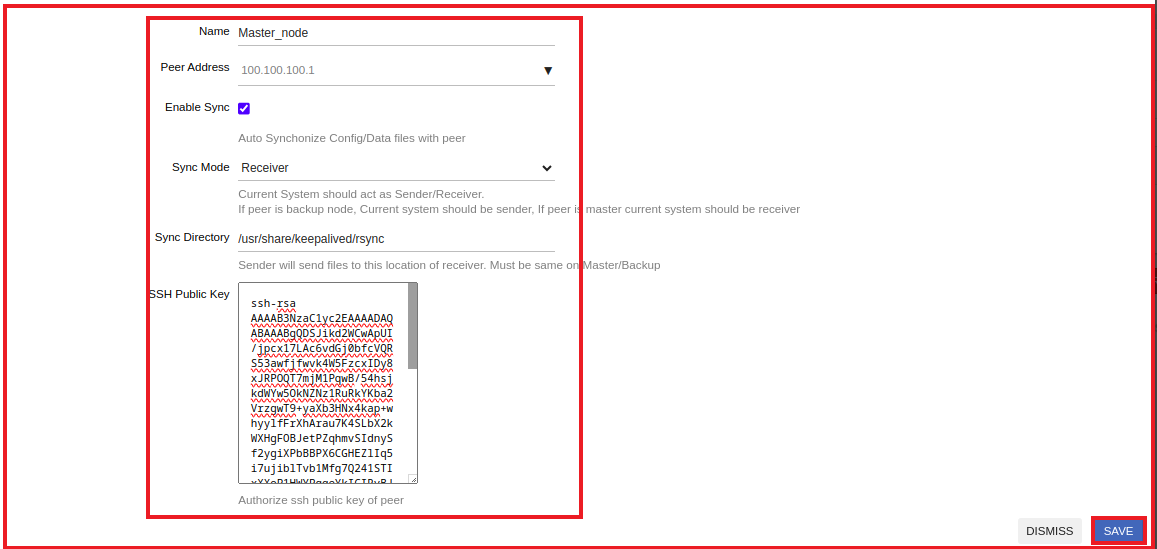
Fill in Sync Details:
-
SSH Mode: Select Sender.
-
sync Director: The sync directory will appear by default.
-
Path SSH Private Key: First go to your local terminal for the path to SSH private key.
-
They gave this command ssh-keygen.
-
After giving the ssh-keygen command, enter 4 times and you will get the key.
# ssh-keygen
Generating public/private rsa key pair.

Enter file in which to save the key (/root/.ssh/id_rsa): Enter passphrase (empty for no passphrase):
Enter same passphrase again:
Your identification has been saved in /root/.ssh/id_rsa
Your public key has been saved in /root/.ssh/id_rsa.pub
The key fingerprint is:
SHA256:4uHsxMYJOH1fmso+h5ew4sH0pAJgmBhQjeV7/PTD9bI root@sharad-Latitude-5480
The key's randomart image is:
+---[RSA 3072]----+
|+..+.            |
|oo...            |
|=.  .            |
|o  o o           |
|. o = B S . .    |
| . + &.B * . .   |
|  . + @+=.+ . .  |
|   ..*+.+  . o   |
|   ..o=+    E    |
+----[SHA256]-----+ -
Then click on Select File. After clicking on Select File, click on browse and select the file.
-
-
Click on the Save button.
-
-
Then click on the SAVE & APPLY button.
-
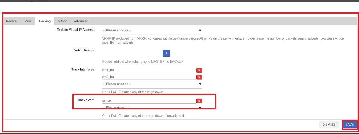
Click on the Instance tab > Edit button.
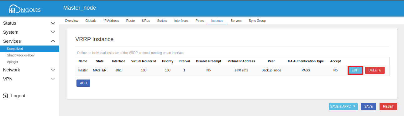
-
Go to the Tracking tab > Navigate to the Track Script and choose the sender. And then click on Save button.
-
Backup_Node
-
Login to the UI:
- Access the Master Node UI using the provided IP address.
-
Navigate to Keepalived:
- From the main menu, go to the Services menu section.
- Select Keepalived menu from the Services menu.
- Click on the Script tab within the Keepalived window.
- Click on the Add button.
-
Fill in Script Details:
- Name: Enter the Name for Ex: sync_ha.
- Script: Click on Select file and choose file(By default file will appear there, you have to select)
- Interval: Interval which will be 60 by default.
- Weight: Enter the Weight for Ex: 100.
- After clicking on the Save button.
-
Click on SAVE & APPLY button to apply the new script configuration.
-
Click on the Add button under the Track Script section.
-
Enter Track Script Details.
- Name: Enter the Name for Ex:recevier
- VRRP Script: Select sync_ha.
- Weight: Enter the Weight for Ex:100.
- After clicking on the Save button.

-
Go to the Peers tab and click on Edit button.
-
Check the Enable Sync box. And proceed to fill in the new fields.
- Fill in Sync Details:
- sync Mode: Select Receiver.
- SSH Public Key: First go to your local terminal for the path to SSH private key.
- They gave this command cat/id-ras.pub. If you give this command, a key will be generated, copy and paste there. After then click on Save button.
- Fill in Sync Details:
-
Then click on the SAVE & APPLY button.

-
Click on the Instant tab > Edit button.
-
Go to the Tracking tab > Navigate to the Track Script and choose the receiver. And then click on Save button.

2.3. Verifying HA Configuration
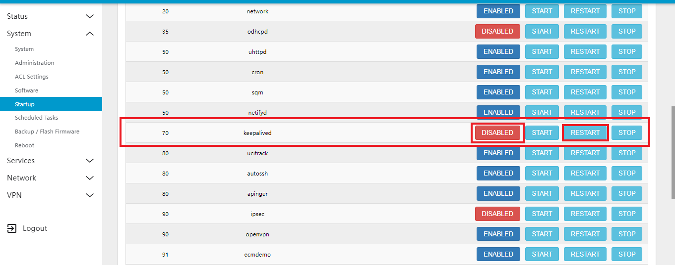
Ensure Keepalived Service is Enabled and Restarted on both nodes
-
Go to System menu > Startup menu. Click on the ENABLED button to keepalive service and click on RESTART button Service.
-
Check service status in CE Command line ps | grep keep.
     ps | grep keep
     3643 root      2188 S    /bin/sh /usr/bin/keepalived-rsync-inotify Backup Mas
     4783 root      3428 S    {keepalive.sh} /bin/sh /usr/bin/keepalive.sh
     11648 root      5812 S    /usr/sbin/keepalived -n -f /tmp/keepalived.conf
     11649 root      5816 S    {keepalived_vrrp} /usr/sbin/keepalived -n -f /tmp/ke
     30512 root      1120 R    grep keep
Check Both Node Status:
- Check if the status on both Master_node and Backup_node matches the expected status as provided.
- Now go to the Services menu and click on Keepalived.
Master_node
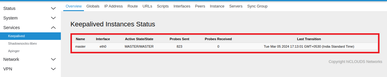
- When the configuration is complete, the status of the Master_node will be displayed as follows:
Upon completion of the configuration, the node status will be as follows:
-
Name: Master
-
Interface: eth0
-
Active Status: Master/Master
-
Probes Sent: 823
-
Probes Received: 0
-
Last Transition: The time, day and date of the last transition will be recorded.
These details will appear in the status output once the configuration is applied. It is important to note that when a node is configured as master, the active status will be displayed as Master/Master.
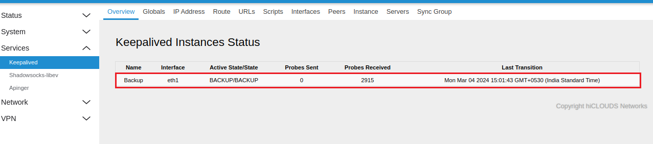
Backup_node
-
Backup_node status will be as follows.
Backup_node_statusUpon completion of the configuration, the node status will be as follows:
-
Name: Backup
-
Interface: eth1
-
Active Status: Backup/Backup
-
Probes Sent: 0
-
Probes Received: 2915
-
Last Transition: The time, day and date of the last transition will be recorded.
These details will appear in the status output once the configuration is applied. It is important to note that when a node is configured as backup, the active status will be displayed as Backup/Backup.
-
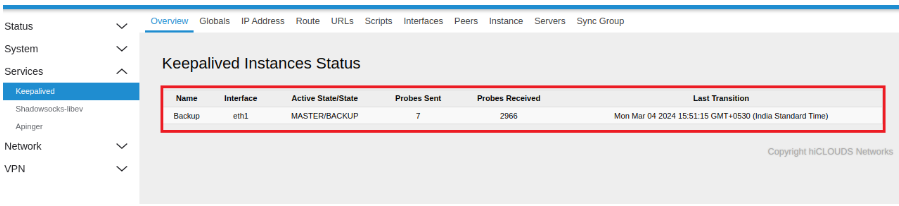
Test Failover:
-
When the Master_node goes off, it will switch to the Backup node's node. Its status will be Master/Backup because the backup will go to the Master_node. And then when the Master_node turns on it will go back to Master/Master.
Failover and Restoration of NodeIn the event that the master node fails or becomes unavailable for any reason, the backup node will automatically assume the role of the master node. During this failover process, the active status will display as Master/Backup.
Once the original master node is restored and the system returns to its normal operational state, the active status will revert to Master/Master. This status will be reflected according to the status check of both nodes.
-
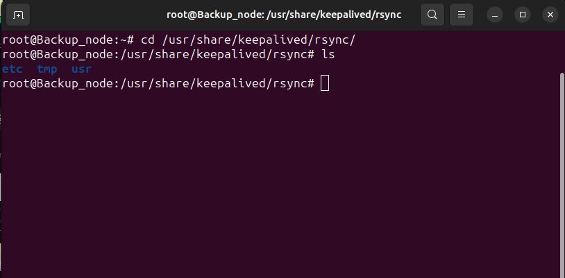
After synchronization, verify that the configuration file from the master node is present on the backup node.
- Enter to the following path:
/usr/share/keepalived/rsync. Ensure that three configuration files are visible in this directory, as indicated in the reference image. If these files are not present, it indicates that synchronization has not been successfully completed.
sync-infoUpon synchronization, the entire configuration state of the master node is replicated to the backup node. This process is triggered when the master node becomes unavailable or experiences a failure.
- Enter to the following path:
FAQ
Q1: Why is a Virtual IP needed?
A virtual IP (VIP) is required to provide an additional IP address layered over the original configured IP address. It allows for network redundancy, load balancing, or high availability by enabling multiple systems or services to share a single IP address, thus facilitating seamless failover or distribution of traffic without requiring changes to the underlying network infrastructure.
Q2: Why is interface tracking required?
Interface tracking is used to monitor the status of network interfaces involved in HA configurations. It helps to dynamically adjust priority levels or trigger failover when a monitored interface goes down, ensuring continuity and reliability of the network services.
Q3: Where is the sync script run from?
The synchronization scripts are executed from the Control Engine (CE), ensuring configurations are consistent across all nodes in the HA cluster.
Q4: Which service works for High Availability (HA)?
The keepalivedservice is used for providing High Availability (HA) in a network environment. It manages virtual IP addresses and handles failover scenarios by monitoring the state of network interfaces and servers.
Q5: How to check the service status?
To check the status of the keepalived service, you can use the following command:ps | grep keepalived
Q6: How to check if HA is synchronized or not?
To check if High Availability (HA) synchronization is successful, you can review the script file located at /etc/keepalived/scripts. Upload and verify the file contents to confirm synchronization status.
Q7: How to restart the keepalived service?
To restart the keepalived service, use the following command:sudo systemctl restart keepalived
Q8: How to view keepalived configuration logs?
The logs for keepalived can be viewed in the system log files using the following command: tail -f /var/log/syslog | grep keepalived
Q9: How to configure a Virtual Router ID (VRID) in keepalived?
The Virtual Router ID (VRID) is configured in the keepalived configuration file, usually located at /etc/keepalived/keepalived.conf.Under the vrrp_instance section, set the virtual_router_id to a unique number for each VRRP instance.
Q10: What is the role of vrrp_script in keepalived?
The vrrp_script directive in keepalived is used to define custom health-check scripts. These scripts periodically check the status of services or network interfaces and adjust the priority of VRRP instances based on their results, thus ensuring optimal failover behavior.
Q11: what is a IPv4 Gateway?
The vrrp_script directive in keepalived is used to define custom health-check scripts. These scripts periodically check the status of services or network interfaces and adjust the priority of VRRP instances based on their results, thus ensuring optimal failover behavior.