PBR
This document provides a step-by-step guide on how to configure, edit, and delete Policy-Based Routing (PBR) rules on a CE (Customer Edge) device through its web interface. PBR allows network administrators to define routing policies based on criteria beyond the destination IP address, such as source IP address, source port, destination IP address, destination port, and input interface.
PBR Rule Column grid Fields Details
| Field | Description |
|---|---|
| Priority | Determines the order of rule evaluation. Lower values have higher priority. |
| Lookup | Specifies the routing table to be used for matching traffic. |
| Input Interface | Interface on which incoming traffic is received and matched against the rule. |
| Output Interface | Interface through which matching traffic will be sent. |
| Source Subnet | Defines the IP address and netmask from where the traffic originates. |
| Destination Subnet | Defines the IP address and netmask to where the traffic is headed. |
| Action | Provides options to edit or delete the IP Rule. |
Creating PBR
-
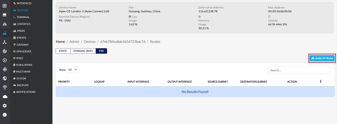
Go to the Login > CE Devices > [Select CE] > ROUTING > PBR > ADD IP Rule.
-
The following parameters need to be configured for the new IP rule:
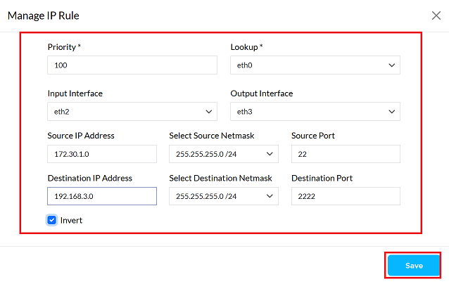
1. Priority:: PBR rules are checked in order of their importance. A lower number indicates a higher importance. The system uses the rule that applies first. Example: 100
2. Lookup: The system determines where the traffic is coming from. This rule will only check traffic coming from that location. Example: eth0
3. Input Interface: Interface where incoming traffic is matched against the rule. Example: eth1
4. Output Interface: An interface used to send out a specific type of traffic. Example: eth2
5. Source IP Address: Using the netmask, you can find a range of IP addresses together with the source IP address. Example: 172.30.1.0
6. Select Source Netmask The netmask, together with the IP address, determines which IP address belongs to which network. Example: 255.255.255.0/24
7. Source Port: Determines which port the traffic originated from, so that it can be identified correctly. Example: 22
8. Destination IP Address: This determines which IP addresses the rule will apply to. Example: 192.168.3.0
9. Select Destination Netmask: Works with destination IP, which determines the list of addresses where data is sent. Example: 255.255.254.0/24
10. Destination Port: Determines which port number data going to a specific location will go to. Example: 2222
11. Invert: If you do not want the rule to apply to certain addresses and ports, you should enable this option. Doing so will cause the rule to apply to all remaining addresses and ports. Action: Check the box to enable inversion.
-
Click the Save button to make the PBR IP rule work on this device.
-
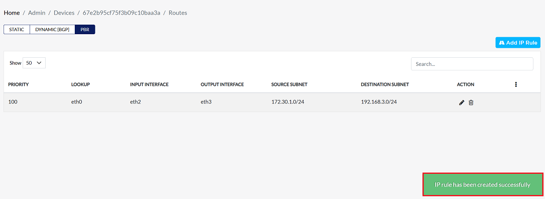
Upon clicking save, a confirmation message IP rule has been created successfully will appear on the screen.
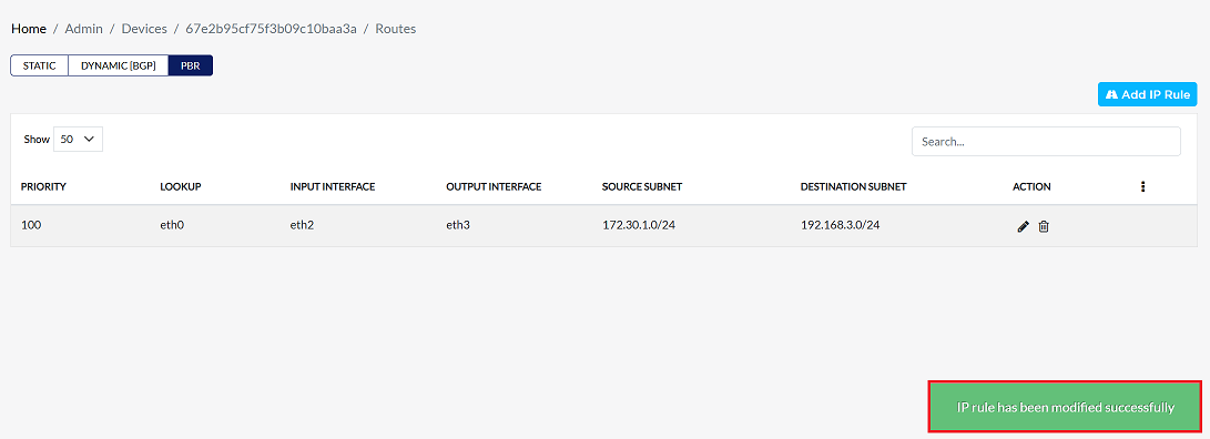
Editing PBR
-
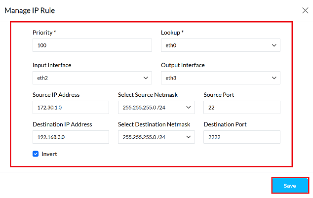
Find the IP rule in PBR and click the Edit button on the right.

-
Update any of the following fields as required Priority, Lookup, Input interface, Output interface, Source IP Address, Select Source Netmask, Source Port, Destination IP Address, Select Destination Netmask, Destination Port , and Invert.
-
Click on the Save button.
-
Upon clicking save, a confirmation message IP rule has been modified successfully will appear on the screen.
Deleting PBR
-
Find the IP rule in PBR and click the Delete button on the right.
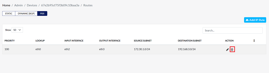
-
Confirm the deletion by clicking Yes in the confirmation dialog.

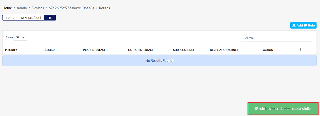
-
Upon successfully deletion, a confirmation message will appear IP rule has been deleted successfully.
Example Scenario
Network Setup:
- PC1 has IP: 172.30.1.100
- Router interfaces:
- eth0: main routing table
- eth1: receives traffic from local LAN
- eth2: connects to a VPN
Goal:
Route all SSH traffic (port 22) on the network through PC1 via the VPN (eth2), instead of the main internet link.
PBR Rule Configuration
| Field | Value |
|---|---|
| Priority | 100 |
| Lookup | eth0 |
| Input Interface | eth1 |
| Output Interface | eth2 |
| Source IP Address | 172.30.1.100 |
| Source Netmask | 255.255.255.0 |
| Source Port | 22 |
| Destination IP | 192.168.3.0 |
| Destination Netmask | 255.255.254.0 |
| Destination Port | 2222 |
| Invert | Unchecked |
Explanation:
When PC1 makes an SSH connection to 192.168.3.0/23 from port 2222, traffic coming on eth1 will go through eth2 (VPN).