CE Link Two different PE, CE2 link PE1, CE2 connected CE
This document outlines the process of connecting CE devices to PE devices and then configuring routing between the different CE devices. The setup includes two CE devices (Demo-CE [CE1] and Apex-CE-London-1 [CE2]) and two PE devices (sha-dev-p1 [PE1] and sha-dev-pe2 [PE2]).
Prerequisites
Before proceeding, ensure the following devices are assigned:
- Assigning CE devices
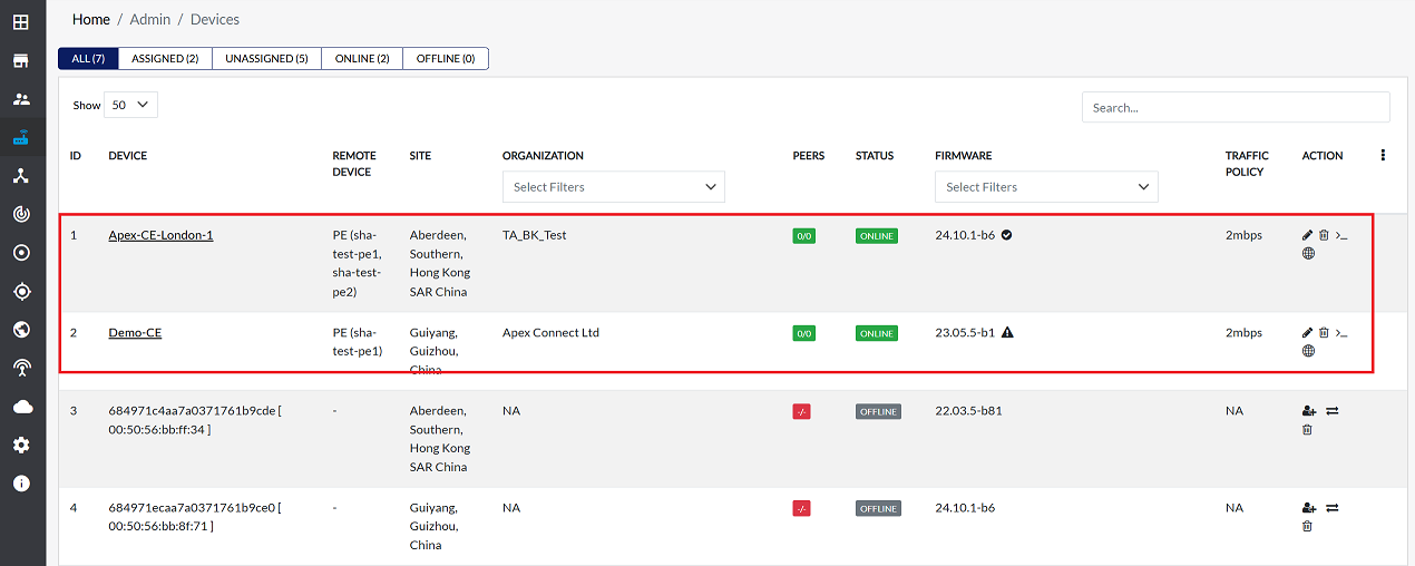
Two CE devices will be required, for example:
- Demo-CE [CE1]
- Apex-CE-London-1 [CE2]
Make sure that these two CE devices are assigned as shown in the image provided. For detailed instructions on how to assign CE devices, please refer to the Assign CE document.
- Assigning PE Devices:
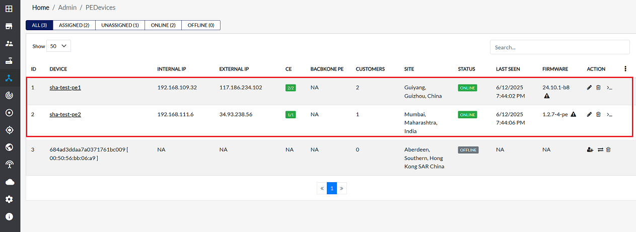
Two CE devices will be required, for example:
- sha-dev-p1 (PE1)
- sha-dev-pe2 (PE2).
Assign these two PE devices as indicated in the image. For comprehensive steps on assigning PE devices, please visit the Assign PE.
Linking CE Devices to PE Devices
Once the CE and PE devices are assigned, linking can be performed. This section describes linking Master-CE [CE1] to two different PE devices and linking Apex-CE [CE2] to a specific PE1 device.
Linking Demo-CE [CE1] to Multiple PE Devices
To link Demo-CE [CE1] to two separate PE devices (PE1 and PE2), follow these steps for each PE:
-
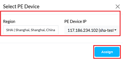
Navigate to Interfaces > VPN > Link PE.
-
Select the Region and the PE device IP (i.e, for PE1, then for PE2).
-
Click the Assign button.
-
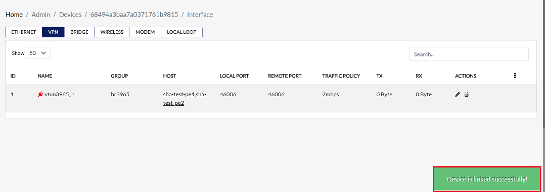
A success message Device linked successfully will appear, and the linked device will be displayed in the VPN interface grid. For more detailed information, refer to the CE Link to three PE document.
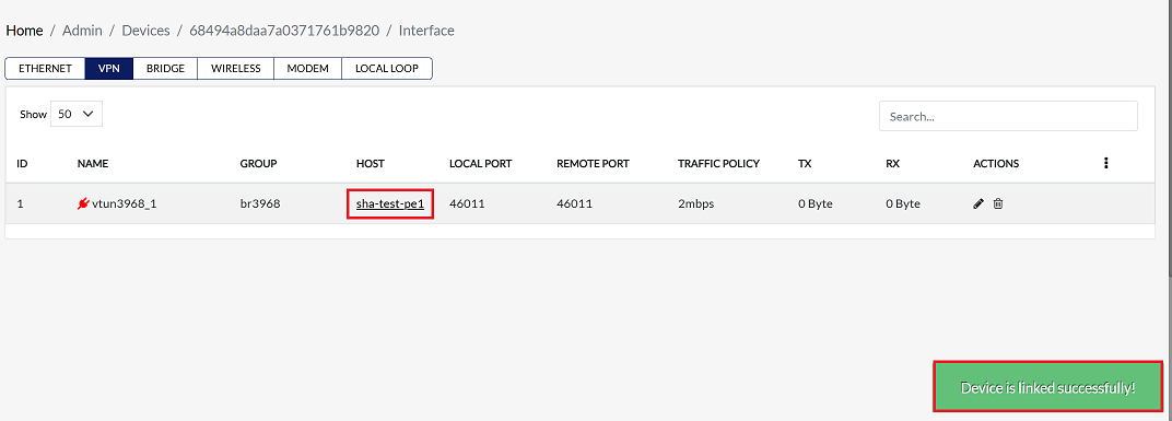
Linking Apex-CE-London-1 (CE2) to sha-test-PE1
Now, link Apex-CE-london-1 (CE2) to sha-test-PE1. Follow the same linking steps outlined above. After successful linking, the connection will be visible in the VPN interface grid, as shown in the provided image.
Route Apex-CE-london-1 Device IP on the Master-CE
On the master-CE device, add the IP address of the Apex-CE-London-1 device to its routing process.
-
Fill in the following details:
- IP address: Enter the IP address of the CE device (i.e., 172.30.1.0)
- Subnet mask: Enter the subnet mask (i.e., 255.255.255.0/24).
- Gateway IP Address: Select the Gateway IP Address (i.e., br25(100.100.100.2)).
- Interface: Select the Interface (i.e., br25).
- Priority: Enter the priority (i.e., 1).
- Then click on Announce Route. (Announce Route is used to route to other devices).
Route Master-CE Device IP on the Apex-CE-london-1 Device
Similarly, on the Apex-CE-london-1 CE device, add the IP address of the Master-CE to the routing process.
- Fill in the following details in the Hub device:
- IP Address: Enter the IP address of the Hub device (i.e., 192.168.1.0).
- Subnet Mask: Enter the subnet mask (i.e., 255.255.255.0/24).
- Gateway IP Address: Select the Gateway IP Address (i.e., br25(100.100.100.2)).
- Interface: Select the Interface (i.e., br25).
- Priority: Enter the priority (i.e., 1).
- For more information about routing, visit the routing doc provided here.