Static
Static routing is traffic defined by routes in the routing table of Customer Edge devices. Data packets then move along a predetermined path to reach their destination. Static routes are best applied in controlled scenarios that require expected and secure network behavior. This guide illustrates how to configure static routes in different contexts such as CE devices with a single Provider Edge, multiple Provider Edges, stand-alone configurations, and hub-and-spoke VPNs.
Two CEs link with PE
Any CE devices connecting to a single PE device rely on proper routing between CE LANs to communicate. Static routes are then configured on each CE to send traffic destined for the other CE's LAN through the gateway specified on the bridge interface.
-
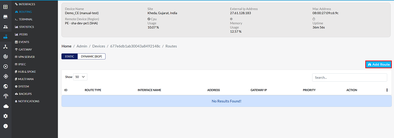
Go to the Login > CE Devices > [Select CE] > ROUTING > STATIC > Add Route.
-
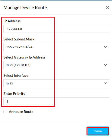
Provide the following information in the respective fields.
- IP Address: Enter the destination IP address for which routing is to be configured. (i.e, 172.30.1.0)
- Select Subnet Mask: Select the appropriate subnet mask for the destination IP. (i.e, 255.255.255.0/24)
- Select Gateway Ip Address: Choose the gateway IP for routing. You can select from: Bridge, Ethernet (eth), Custom (manually specify a gateway) For (i.e, br25(172.31.0.1)). In this situation, where a bridge interface allows inter-CE communication, the gateway IP should be the IP address assigned to the bridge interface itself. For example, in the case where this bridge interface br38 has the 100.100.100.2, it should be selected as the gateway. Worth to remember: The bridge interface must have an IP address assigned.
- Select Interface: Select the network interface through which traffic will be routed. (i.e, br25). When two CE devices are connected to one PE device through a set of links, and they need to be connected for communication between the LANs of the two CE devices, a bridge interfce needs to be used. Bridge interface should be used when two CEs connected on the same PE have to communicate between their respective LANs.
- Enter Priority: Specify the priority for this route. Lower values indicate higher priority. (i.e, 1)
- Click on the Save button.
-
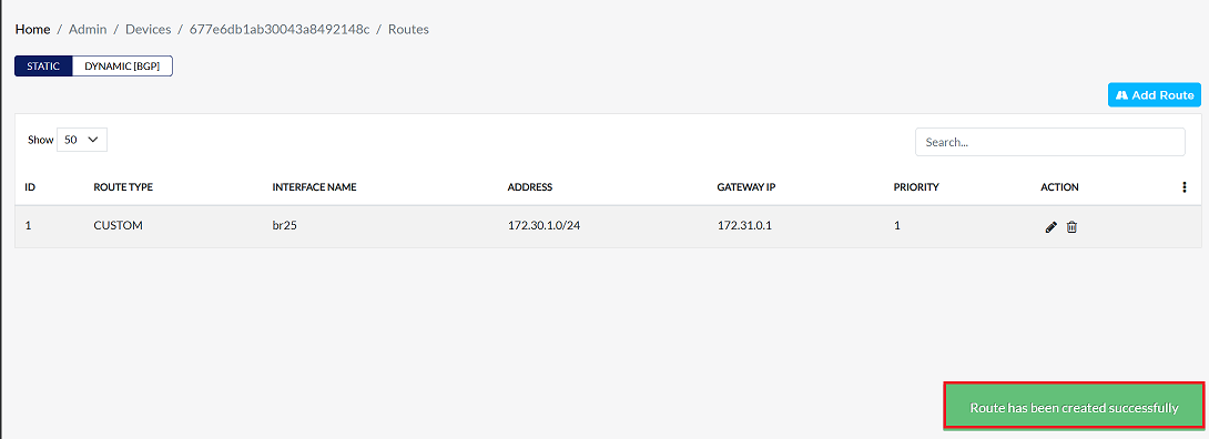
Upon successfully configuration, a confirmation message will appear Route has been created successfully
Two CEs connect with different PEs
The process of connecting CEs on different PEs to the LAN is known as "two CEs connected to different PEs". How to accomplish this is described below.
-
Go to the Login > CE Devices > [Select CE] > ROUTING > STATIC > Add Route.
-
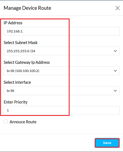
Provide the following information in the respective fields.
- IP Address: Enter the destination IP address for which routing is to be configured. (i.e, 192.168.1.0)
- Select Subnet Mask: Select the appropriate subnet mask for the destination IP. (i.e, 255.255.255.0/24)
- Select Gateway Ip Address: Choose the gateway IP for routing. You can select from: Bridge, Ethernet (eth), Custom (manually specify a gateway). (i.e, br38(100.100.100.2)). In this situation, where a bridge interface allows inter-CE communication, the gateway IP should be the IP address assigned to the bridge interface itself. For example, in the case where this bridge interface br38 has the 100.100.100.2, it should be selected as the gateway. Worth to remember: The bridge interface must have an IP address assigned.
- Select Interface: Select the network interface through which traffic will be routed. (i.e, br38). Bridge interface should be used when two CEs connected on the same PE have to communicate between their respective LANs.
- Enter Priority: Specify the priority for this route. Lower values indicate higher priority. (i.e, 1)
- Click on the Save button.
- Upon successfully configuration, a confirmation message will appear Route has been created successfully
Static Routing for stand alone CE
- Static routing is used when a CE device is not dependent on any protocol and is configured to communicate directly with other CE devices or a specific network. This configuration manually defines the gateway and interface to reach a specific destination network.
Steps to Configure a Static Route
The steps below explain the process for adding a static route on a CE device:
-
Go to the Login > CE Devices > [Select CE] > ROUTING > STATIC > Add Route.
-
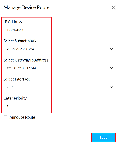
Provide the following information in the respective fields.
- IP Address: Enter the destination IP address for which routing is to be configured. (i.e, 192.168.1.0)
- Select Subnet Mask: Select the appropriate subnet mask for the destination IP. (i.e, 255.255.255.0/24)
- Select Gateway Ip Address: Choose the gateway IP for routing. You can select from: Bridge, Ethernet (eth), Custom (manually specify a gateway). (i.e, eth3(172.30.1.154)). In this situation, where a ethernet interface allows inter-CE communication, the gateway IP should be the IP address assigned to the ethernet interface itself. For example, in the case where this ethernet interface eth3 has the 172.30.1.154, it should be selected as the gateway. Worth to remember: The ethernet interface must have an IP address assigned.
- Select Interface: Select the network interface through which traffic will be routed. (i.e, eth3). When configuring CE devices to communicate with Provider Edge (PE) devices, the normal practice is to set up Ethernet interfaces to route directly to physical network equipment.
- Enter Priority: Specify the priority for this route. Lower values indicate higher priority. (i.e, 1)
- Click on the Save button.
- Upon successfully configuration, a confirmation message will appear Route has been created successfully
OpenVPN Hub Spoke site-to-site CE
The steps to configure Static Routing in an OpenVPN Hub-Spoke Site-to-Site CE (Customer Edge) setup are explained here in an informative manner. In this setup, static routes are required to properly route traffic between spokes through the hub or from the spoke to the hub network.
To configure static routing for a CE device in a hub-spoke setup, follow these steps:
-
Go to the Login > CE Devices > [Select CE] > ROUTING > STATIC > Add Route.
-
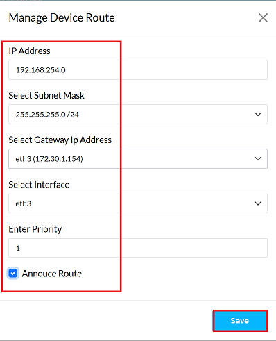
Provide the following information in the respective fields.
- IP Address: Enter the destination IP address for which routing is to be configured. (i.e, 192.168.254.0)
- Select Subnet Mask: Select the appropriate subnet mask for the destination IP. (i.e, 255.255.255.0/24)
- Select Gateway Ip Address: Choose the gateway IP for routing. You can select from: Bridge, Ethernet (eth), Custom (manually specify a gateway). (i.e, eth3(172.30.1.154)). In this situation, where a ethernet interface allows inter-CE communication, the gateway IP should be the IP address assigned to the ethernet interface itself. For example, in the case where this ethernet interface eth3 has the 172.30.1.154, it should be selected as the gateway. Worth to remember: The ethernet interface must have an IP address assigned.
- Select Interface: Select the network interface through which traffic will be routed. (i.e, eth3). When configuring CE devices to communicate with Provider Edge (PE) devices, the normal practice is to set up Ethernet interfaces to route directly to physical network equipment.
- Enter Priority: Specify the priority for this route. Lower values indicate higher priority. (i.e, 1)
- Annouce Route: Check this option if you want the route to propagate to other connected devices.
- Click on the Save button.
- Upon successfully configuration, a confirmation message will appear Route has been created successfully
IPSec Hub Spoke site-to-site CE
The following steps outline the procedure for configuring a static route to a customer edge (CE) device in an IPSec hub-spoke topology. This setup enables seamless communication between CE devices and provider edge (PE) devices or other CE devices.
-
Go to the Login > CE Devices > [Select CE] > ROUTING > STATIC > Add Route.
-
Provide the following information in the respective fields.
-
IP Address: Enter the destination IP address for which routing is to be configured. (i.e, 192.168.254.0)
-
Select Subnet Mask: Select the appropriate subnet mask for the destination IP. (i.e, 255.255.255.0/24)
-
Select Gateway Ip Address: Choose the gateway IP for routing. You can select from: Bridge, Ethernet (eth), Custom (manually specify a gateway). (i.e, eth3(172.30.1.154)). In this situation, where a ethernet interface allows inter-CE communication, the gateway IP should be the IP address assigned to the ethernet interface itself. For example, in the case where this ethernet interface eth3 has the 172.30.1.154, it should be selected as the gateway. Worth to remember: The ethernet interface must have an IP address assigned.
-
Select Interface: Select the network interface through which traffic will be routed. (i.e, eth3). When configuring CE devices to communicate with Provider Edge (PE) devices, the normal practice is to set up Ethernet interfaces to route directly to physical network equipment.
-
Enter Priority: Specify the priority for this route. Lower values indicate higher priority. (i.e, 1)
-
Annouce Route: Check this option if you want the route to propagate to other connected devices.
-
Click on the Save button.
-
Upon successfully configuration, a confirmation message will appear Route has been created successfully.
-
Add Third CE Device to Network
The incorporation of a third Customer Edge (CE) device in the network refers to the addition of another CE router or equivalent device in an existing network topology. Adding a CE device to the network demands configuring and establishing static routes directedto particular destinations. The idea is to route packets in the defined network paths for optimal performance and reliability. This kind of routing is especially useful in small or static networks without the need for dynamic routing protocols.
- Go to the Login > CE Devices > [Select CE] > ROUTING > STATIC > Add Route.
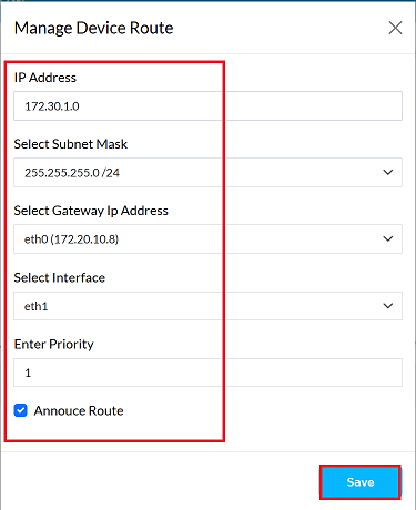
- Provide the following information in the respective fields.
-
IP Address: Enter the destination IP address for which routing is to be configured. (i.e, 172.30.1.0)
-
Select Subnet Mask: Select the appropriate subnet mask for the destination IP. (i.e, 255.255.255.0/24)
-
Select Gateway Ip Address: Choose the gateway IP for routing. You can select from: Bridge, Ethernet (eth), Custom (manually specify a gateway). (i.e, eth0 (172.20.10.8)). The gateway IP must align with the WAN IP configuration.
-
Select Interface: Select the network interface through which traffic will be routed. (i.e, eth0). When configuring CE devices to communicate with PE devices, the normal practice is to set up Ethernet interfaces to route directly to physical network equipment.
-
Enter Priority: Specify the priority for this route. Lower values indicate higher priority. (i.e, 1)
-
Annouce Route: Check this option if you want the route to propagate to other connected devices.
-
Click on the Save button.
-
Upon successfully configuration, a confirmation message will appear Route has been created successfully.
-
Ediing Route
To update the details of any static route, follow these steps:
-
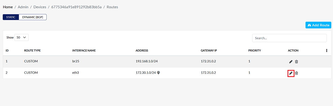
Click on the Edit option in the 'Action' column on the right side of the row of the Static Routing to be edited.
-
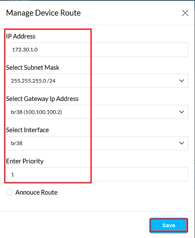
Edit the static route details as needed. The following details can be updated:
- IP Address: To change the network route, enter the new destination IP address. The new IP address will define the network segment to which the routing will be directed. For instance, if the previous IP was 172.30.1.0, it has been updated to 172.30.2.0. Changing the IP address inherently changes the network route.
- Subnet Mask: The subnet mask can be changed here if required for the new network configuration.
- Gateway IP: If a different gateway is needed for the routing configuration, the gateway IP address can be updated.
- Interface: The network interface to be used for this route can be selected and changed if necessary.
- Priority: If necessary, the priority for this route can be updated by entering a new value.
In the recent update, only the IP address needed to be changed, as the routing destination needed to be modified. IP Address: Changed from 172.30.1.0 to 172.30.2.0. Other details: Subnet Mask, Gateway IP, Interface, and Priority details have been kept as they were. (No changes have been applied to these fields).
-
After making all the necessary changes, verify the updated configuration and then click the Save button to apply the new settings and make them effective.
-
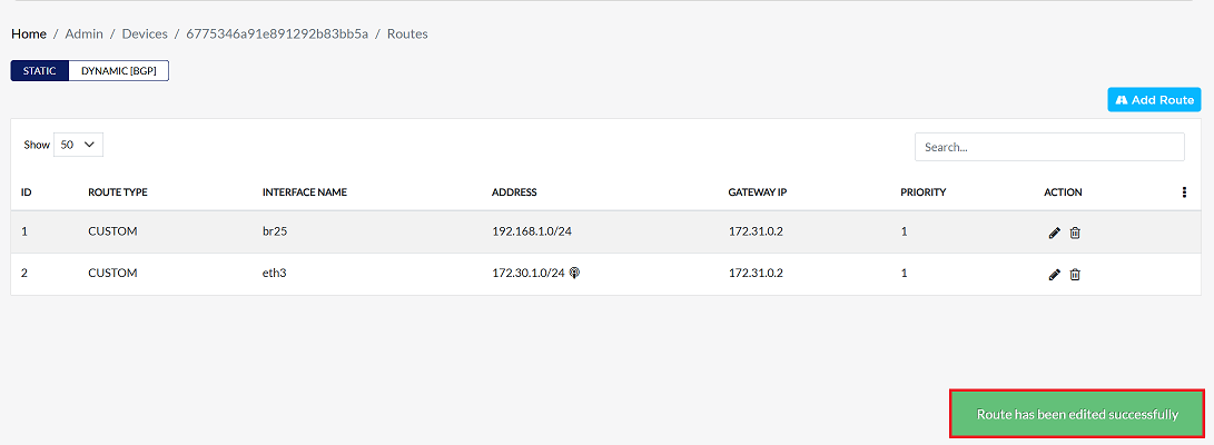
Upon successfully configuration, a confirmation message will appear Route has been edited successfully
Deleting a Route
To delete the details of any static route, follow these steps:
-
Click on the delete option in the 'Action' column on the right side of the row of the Static Routing to be edited.

-
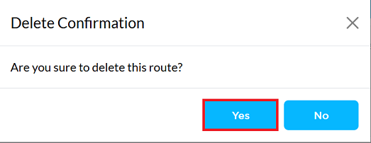
By clicking on the Delete option, a confirmation message popup will open on the screen. This popup asks to confirm the deletion action again, which prevents accidental deletion.
- The static route has two options available:
- Confirm Delete: If the static route really wants to delete the information, click on the Yes button in the popup.
- Cancel Delete: If not intended to delete or clicked by mistake, click on the No button to cancel the action and keep the information safe.
- The static route has two options available:
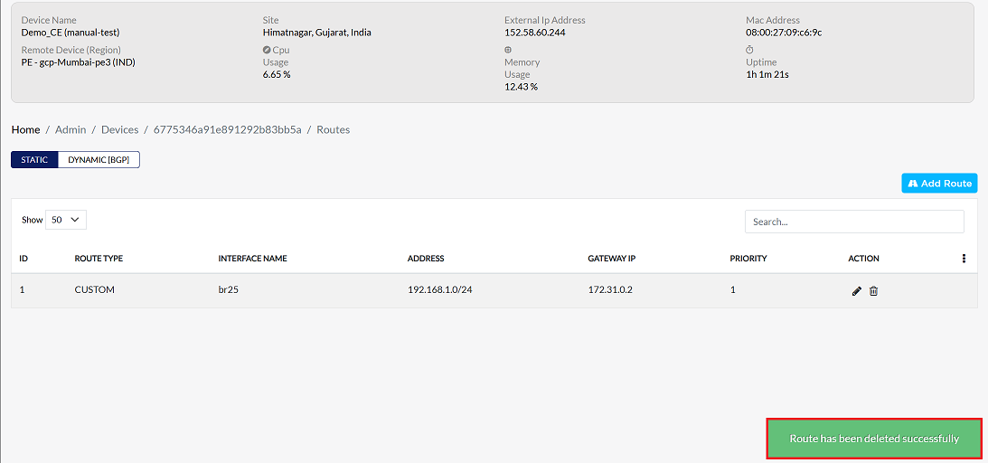
Decision taken in the image As mentioned, the Yes button has been clicked in the image. This means that the deletion action has been confirmed by the static route and the relevant data will be removed from the system.
-
Upon successfully deletion, a confirmation message will appear Route has been deleted successfully